Autodesk Forge Viewer
The Autodesk Forge Viewer in BIMWorkplace allows you to visualize, navigate, inspect, measure, annotate, and review models directly in the cloud.
It provides a consistent environment for model-based coordination, analysis, and communication, without requiring authoring software licenses.
The viewer used in each project is defined in Project Settings > Configurations. This article refers specifically to the Autodesk Forge Viewer.
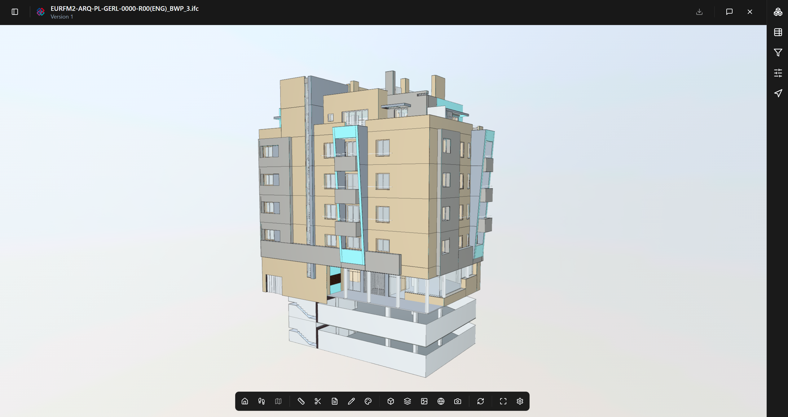
Viewer navigation tools
Viewer navigation tools control how you move through and interact with the model in 3D space.

Home View
Use Home View to return the camera to the default model position.
This is useful when you need to reset the view after navigating, zooming, sectioning, or isolating parts of the model.
Walk Mode
Use Walk Mode to navigate through the model as if you were walking inside the building.
This mode is useful for reviewing rooms, corridors, technical spaces, circulation areas, and spatial relationships from an immersive perspective.
Minimap
The Minimap is available only in Walk Mode.
Use it to understand your current position inside the model and navigate more easily through large or complex buildings.
Analysis and review tools
These tools help you inspect model geometry, validate information, and review specific project areas.

[Screenshot: Viewer toolbar highlighting Measure, Section, 2D Sheets, Markup, and Colorize Elements.]
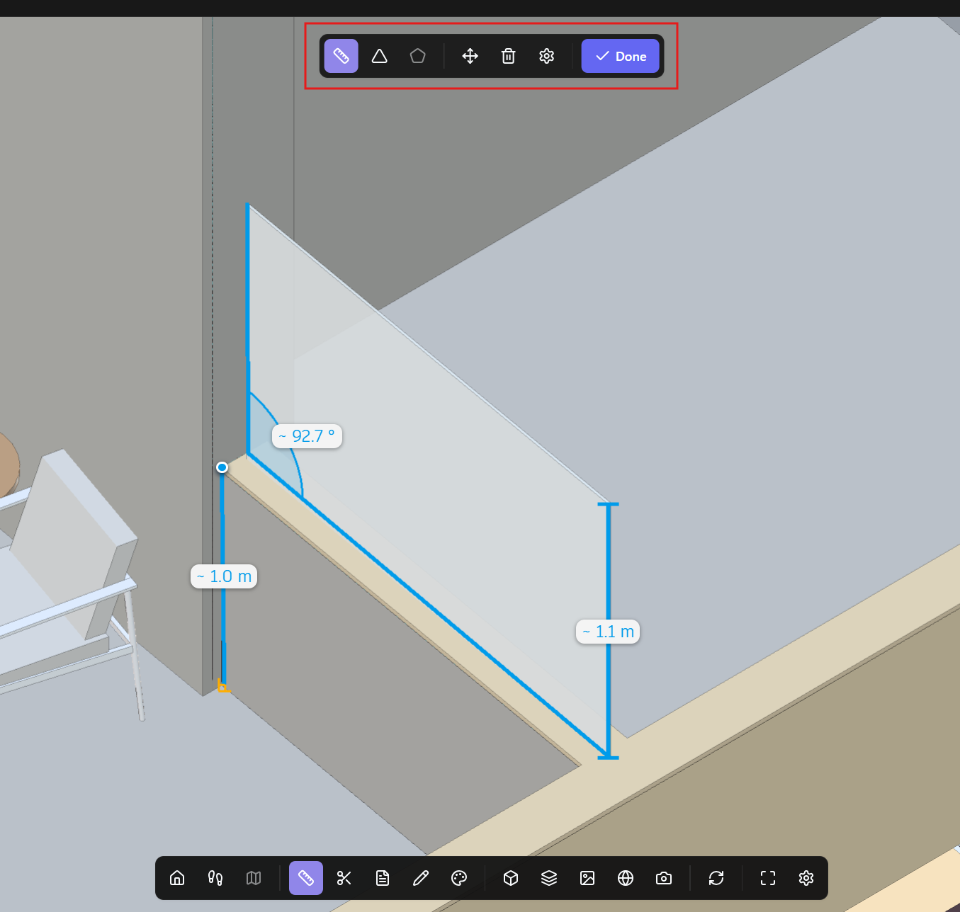
Measure
Use Measure to check distances and angles directly in the model or in 2D sheets.
In 3D views, Measure supports distance and angle measurements.
In 2D views, Measure supports distance, angle, and area measurements.
You can also calibrate measurements using a known real-world distance and delete measurements that are no longer needed.
Section
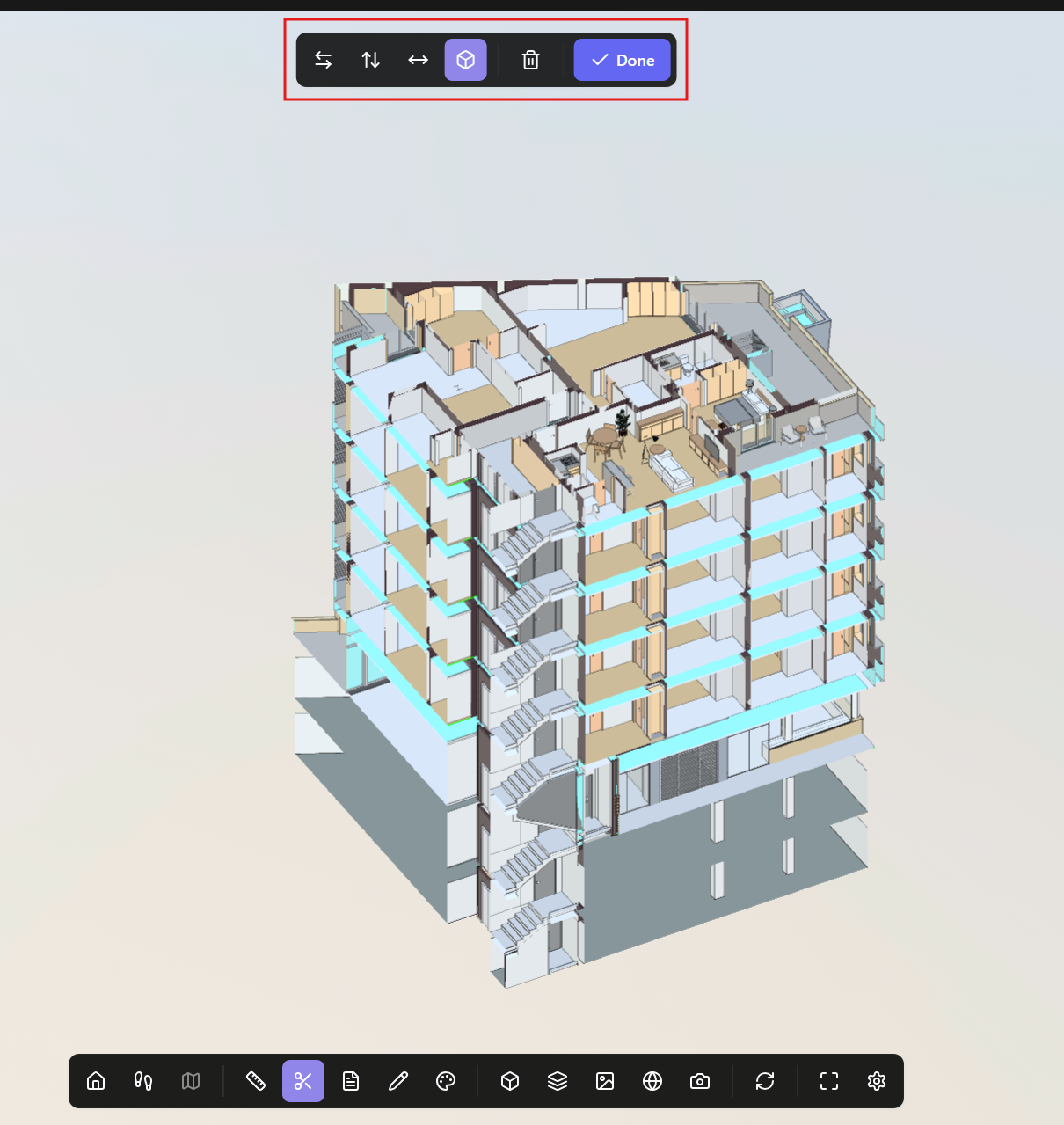
Use Section to cut through the model and inspect internal geometry.
Sections can be created along the X, Y, or Z axis, depending on the direction you need to analyze.
You can also use a complete Section Box to isolate and review a specific 3D portion of the model from multiple directions.
Section tools are useful for reviewing hidden elements, technical spaces, shafts, ceilings, MEP coordination areas, and complex assemblies.
2D Sheets
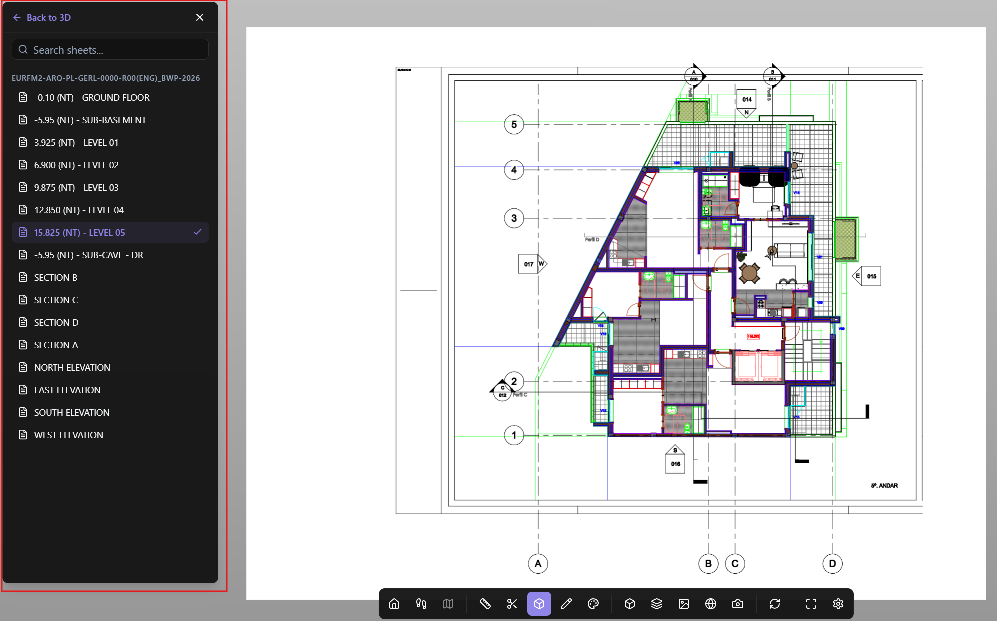
Use 2D Sheets to access and review sheets that were imported together with the model.
This is commonly available in models that include sheets, such as Revit models.
2D Sheets allow users to review project documentation directly in the viewer and move between model-based review and sheet-based review without leaving BIMWorkplace.
Markup
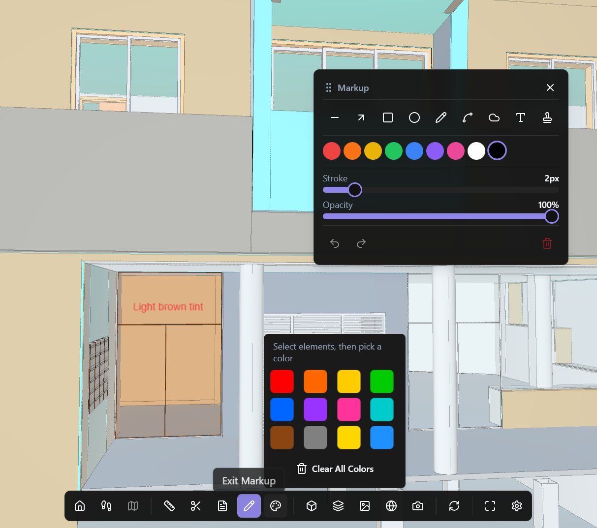
Use Markup to add visual annotations to the current viewer image when creating a topic in the Design module.
Markups help emphasize specific areas, issues, or observations before saving the image as part of the topic context.
Colorize Elements
Use Colorize Elements to visually emphasize selected model elements when creating a topic in the Design module.
This helps make the topic image clearer by highlighting the elements related to the issue, request, suggestion, or observation being reported.
Visualization modes and model context
These tools change how the model is displayed or contextualized in the viewer.

Orthographic
Use Orthographic mode to remove perspective distortion from the model view.
This is useful for technical review, alignment checks, and clearer geometric analysis.
AI Render
Use AI Render to generate an AI-assisted visual representation based on the current model view.
This can support presentations, design communication, and visual exploration.
Viewer maintenance
Rebuild Viewer
Use Rebuild Viewer to reload or rebuild the viewer when the model display needs to be refreshed.
This can be useful after model updates, display inconsistencies, or changes that require the viewer to reload the visual environment.

Viewer display options
Fullscreen
Use Fullscreen to expand the viewer across the entire screen.
Click the same button again to exit fullscreen mode.
Viewer Settings
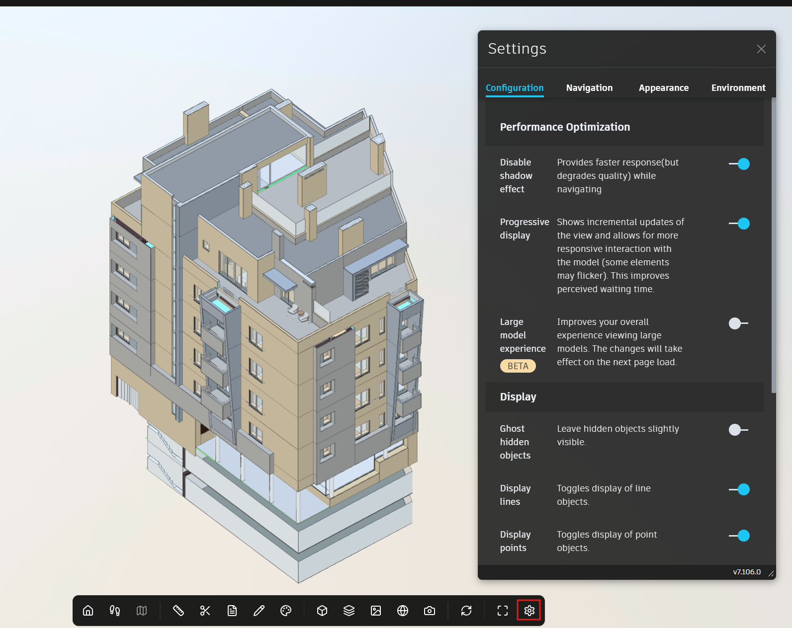
Viewer Settings allow you to control visualization and interaction preferences in the model viewer.
Settings may include configuration, navigation, appearance, and environment options.
Use Restore all default settings to reset the viewer configuration at any time.
Element context menu
In addition to the main viewer toolbar, the Autodesk Forge Viewer also provides a context menu for selected model elements.
When an element is selected, right-click it to open the element context menu.
This menu provides quick access to common actions for inspecting, isolating, hiding, focusing, rotating, and sectioning selected model elements.
![Right-click context menu open on a selected model element with submenu open with Section options.]](https://svwpkiotdzcxsmuprvyf.supabase.co/storage/v1/object/public/blog-covers/inline/06bdd269-1015-4e70-b622-61f228240d54.png)
Show Properties
Use Show Properties to open the properties panel for the selected element.
This allows you to inspect the element’s available metadata and model information.
Isolate
Use Isolate to display only the selected element or selected group of elements.
This is useful when you need to focus on a specific component without visual interference from the rest of the model.
Hide Selected
Use Hide Selected to temporarily hide the selected element from the current view.
Show All Objects
Use Show All Objects to restore the visibility of hidden or isolated elements.
Focus
Use Focus to move the camera directly to the selected element.
This helps quickly locate and inspect an element in the model.
Pivot
Use Pivot to set the selected element as the orbit reference point.
This makes navigation easier when reviewing a specific object or area.
Clear Selection
Use Clear Selection to remove the current element selection.
Section
Use Section to create a section based on the selected element context.
Available options include:
Section Box
Use Section Box to create a cutting box around the selected area.
Section Plane
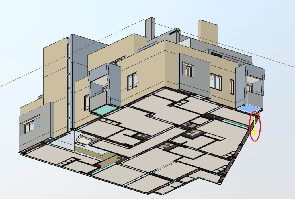
Use Section Plane to create a cut aligned with the side of the element you clicked. The section plane axis depends on the clicked face.
For example, if you select the underside of a ceiling, the section will be created on the Z axis, aligned with the bottom face of that ceiling. This allows you to create precise cuts directly from the selected model element.
Was this article helpful?