Let’s now get to know the main page of the Explorer module. Next, we will describe the various components of the page, listed in the image below.
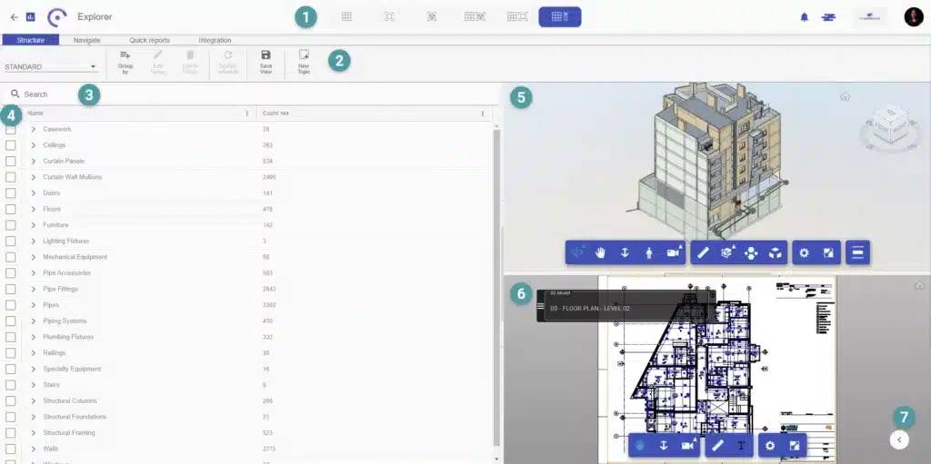
1 – Display method – this tab contains all display and screen splitting options. You can choose to view only the topics, the 3D model or the 2D model, or if you prefer, you can also choose to combine the various views, as in the image above.
2 – Menu – the menu contains the module’s main tools, subdivided into: functionality structure, module navigation, quick reports and integration.
3 – Search – the search bar allows you to search for a specific element or property.
4 – Table of elements – this table shows all the elements organized in a hierarchical structure of category, family and type, with the element count in front. Forms of organization of information can be created with the grouping tool.
5 – 3D Viewer – this viewer allows browsing the 3D model, as well as carrying out measurements and sections, through the navigation toolbar.
6 – 2D Viewer – This viewer allows navigation in the 2D model as well as extracting measurements. Through it, it is possible to visualize the Floor Plans and Sheets, not applying to the PDF format.
7 – Models management bar – this sidebar includes template management, filter options, properties and navigation in the various template environments.
Now that you’re familiar with this module, let’s start exploring all the features!